June 4, 2026 esp32 cyd ina226 power-analyzer lvgl wifi
TL;DR:
I turned a Cheap Yellow Display (CYD / ESP32-2432S028) into a small power analyzer for my bench: an INA226 on I2C measures V/I/P, the CYD shows live numbers on the LCD, pushes JSON over UDP, serves a web dashboard, and prints useful lines on serial. You can change Wi-Fi from the touch UI (gear → scan → virtual keyboard → save to flash), reboot from HTTP / LCD / serial, and run an automated reliability test that power-cycles the board through a USB relay while proving Wi-Fi came back (UART + HTTP). The project is open on GitHub as cyd-power-analyzer; release v1.0 is tagged with a green-build test baseline (100/100 PASS).
What is CYD Power Analyzer?
It is a firmware + host-tooling project for a portable power readout glued to the kind of hardware I keep on my desk: mini-PCs, routers, HDMI splitters, set-top boxes — anything where I want to know how many watts something draws right now, without dragging out a bench DMM and clamp meter every time.
The “meter head” is a CYD module: ESP32, 2.8″ TFT, and a resistive touch controller. A small INA226 breakout sits in the high side of the load power path (100 mΩ shunt on the module I used). The CYD reads the sensor, renders Vbus / I / P on screen, and mirrors the same values to the network.
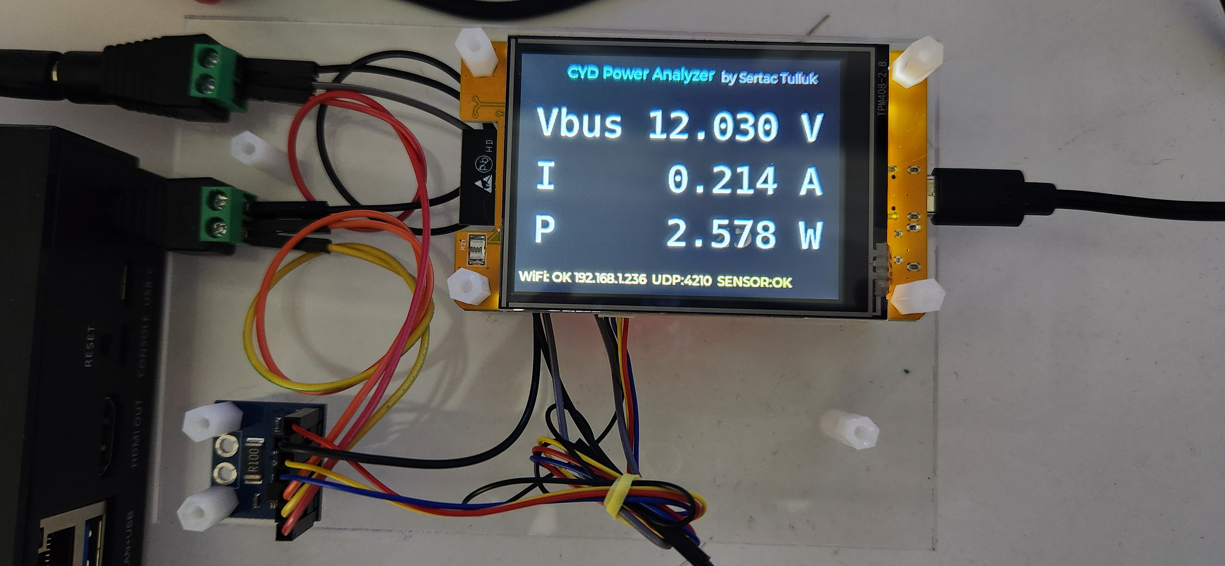
Here is the close-up on a little acrylic plate — CYD, INA226, and the device under test sharing the same 12 V feed:
And the wider bench context (ZBOX, router, splitter, CYD in the middle of the rat’s nest):
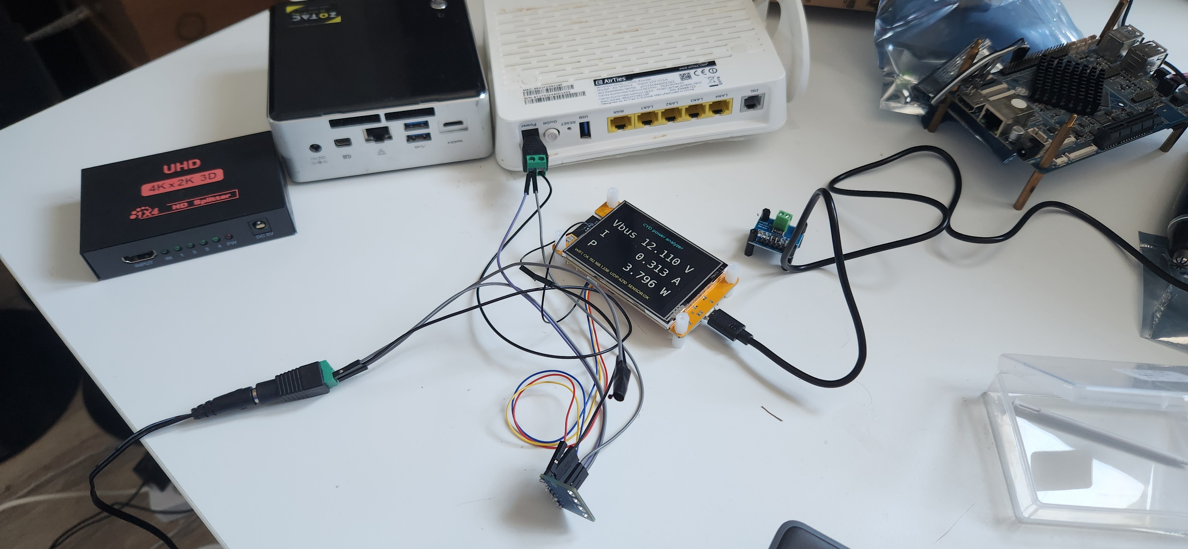
Typical numbers on my 12 V bench supply at the time of the photos: about 12.0 V, 0.2–0.3 A, ~2.5–3.8 W depending on what the load was doing. Footer line on the LCD looked like:
WiFi: OK 192.168.1.236 UDP:4210 SENSOR:OK
Why bother?
I had three practical goals:
- See power at a glance while developing or soak-testing other gear.
- Log remotely — UDP JSON every ~200 ms when Wi-Fi is up, plus HTTP
/api/metricsfor scripts and a browser tab. - Stop guessing about Wi-Fi on cold boot — the CYD sometimes failed to join my AP on first power-up (~2/10 in manual tries). That needed a repeatable test, not “unplug it again and hope”.
The CYD is cheap, already has a display, and Wi-Fi — so it became the UI and the logger, not just a sensor dongle.
Hardware wiring
The firmware expects INA226 at I2C address 0x40:
| Signal | CYD GPIO | Notes |
|---|---|---|
| SDA | GPIO27 | CN1 |
| SCL | GPIO22 | CN1 / P3 |
| GND | CYD GND | common with INA226 |
| 3V3 | CYD 3.3 V | INA226 logic |
On this CYD variant GPIO21 is the TFT backlight — do not use it for I2C.
Shunt on my module is R100 (0.1 Ω). Firmware constants:
static constexpr float kIna226ShuntOhms = 0.1f;
static constexpr float kIna226MaxExpectedAmps = 0.8f;
With 100 mΩ the INA226 shunt ADC tops out around 0.82 A linearly; fine for router/STB-class loads, not for a gaming GPU.
Bus voltage decode uses the mask TI expects — do not use (raw >> 3) * 1.25 mV
or you under-read by roughly 8× (I learned that the hard way on serial METRIC
lines).
Firmware — what it does today
Built with PlatformIO / Arduino on ESP32, LVGL 8 + TFT_eSPI, touch via XPT2046.
| Area | Behaviour |
|---|---|
| LCD | Landscape 320×240; large monospace V / I / P; footer for Wi-Fi + sensor |
| Web | http://<ip>/ dashboard; GET /api/metrics JSON; Reboot device button |
| UDP | Subnet broadcast JSON on port 4210 (~5 Hz) |
| Serial | 115200: STATS, METRIC, INA226_RAW, WIFI ip=... |
| Wi-Fi | Build-time defaults from wifi.env; runtime overrides in NVS |
| Settings UI | Gear icon → BACK / WIFI SETTINGS / RESET WIFI / REBOOT |
| Wi-Fi setup | Scan APs, pick SSID, virtual keyboard for PSK, save to flash |
| Reboot | GET /api/reboot, LCD button, or serial line REBOOT |
Touch entry is only through the small gear — not the whole screen — so you can still read metrics without accidentally opening settings.
Example serial after connect:
WIFI ip=192.168.1.240 udp_bcast_port=4210 gw=192.168.1.1
METRIC vbus_v=11.830 i_a=0.253 p_w=3.000 ...
Example HTTP metrics:
{"vbus_v":11.830,"i_a":0.253,"p_w":3.000,"ms":35340,"cpu":33,"ram":40,
 "sensor_ok":true,"sensor":"ina226","error":"ok","ip":"192.168.1.240"}
Build and flash (Docker-first)
I do not install PlatformIO on the host. The repo ships:
./indockerbuild.sh
ESPPORT=/dev/serial-cyd ./indockerflash.sh
Wi-Fi credentials for the default build live in wifi.env (gitignored); there is
a wifi.env.example. On the device, saved SSID/PSK in NVS override those defaults
until you hit RESET WIFI.
The Wi-Fi reliability harness (tests/cydtest.py)
Manual “power off, power on, did it join?” was getting old. I copied the architecture from a HueBridge test project I use at work (Serial-Auto-Test style):
devices.json— serial port, relay IP, baud rateTEST_RESULTS/test_results.db— SQLite per iterationTEST_RESULTS/results.html— themed HTML dashboardTEST_RESULTS/serial_uart_log/*.txt— timestamped UART capture
Two reboot strategies:
| Mode | What happens |
|---|---|
| soft | GET /api/reboot if the board is on-net; else serial REBOOT (USB-serial stays up) |
| hard | Tasmota-style relay Power OFF / Power ON — kills USB-serial too; script waits for /dev/serial-cyd and re-opens |
| brownout | Same relay path but 200 / 300 / 500 ms OFF (incomplete power events) |
| both | soft then hard (default batch) |
Pass criteria per iteration: firmware prints WIFI ip=<addr> on UART and
GET http://<addr>/api/metrics returns JSON.
My bench relay (wfusb) is at 192.168.1.169:
# same idea as the curl aliases in my shell
curl 'http://192.168.1.169/cm?cmnd=Power%20OFF'
curl 'http://192.168.1.169/cm?cmnd=Power%20ON'
Example run:
cd tests
python3 cydtest.py --mode both -n 10
python3 cydtest.py --mode hard --off-seconds 180 -n 10   # 3 minutes OFF, then ON
Hard mode alternates 1 s OFF and 10 s OFF every iteration unless you
pass --off-seconds for a fixed duration.
Test results (why I tagged v1.0)
I froze a green-build baseline under tests/green-build/v1.0/ and tagged
v1.0 on
GitHub so I can roll back firmware + known-good test artifacts if a future change
breaks Wi-Fi or the sensor path.
Certified automated runs (all PASS, serial + HTTP proof):
| Run | Mode | Iterations | Result |
|---|---|---|---|
| 4 | both (soft + hard) | 20 | 20/20 |
| 5 | both | 60 | 60/60 |
| 6 | brownout | 20 | 20/20 |
| 7 | hard, 3 min OFF | 10 | 10/10 |
Total certified: 110/110 in automation. Connect times were usually ~4–7 s after power-on; worst seen in the long OFF run was still under 5 s.
Interesting finding: under clean relay power cycles (1 s, 10 s, 200–500 ms, even 3 minutes OFF) I could not reproduce the ~20% cold-boot Wi-Fi failure I sometimes see when I manually plug power. My guess is contact bounce / slow rail rise on hand-plugged supplies — not something the firmware alone can fix, but now I have a harness to keep checking after each change.
What is next
Still on the list:
- SoftAP / captive portal when STA fails for a long time (TODO 4 in the repo)
- Maybe mirror Wi-Fi settings on the web UI
- STEO PMON PCB integration (Rev A1 schematic lives in the repo tree as reference hardware — separate from the CYD breadboard bring-up)
Links
- Project: https://github.com/stulluk/cyd-power-analyzer
- Release v1.0: https://github.com/stulluk/cyd-power-analyzer/releases/tag/v1.0
- INA226 datasheet and register math — see
README.mdin the repo (bus voltage masking note is worth reading if you roll your own driver)
If you build one, start with the serial probe firmware
(firmware/ina226_serial_probe/) to verify I2C and shunt wiring before fighting
LVGL and Wi-Fi at the same time. That saved me a few evenings.